








Choosing the right Robot Capacitor is a practical power-design decision, not a simple catalog search. A capacitor may look suitable on paper, yet fail during sudden acceleration, repeated braking, or high-temperature operation.
Dr. John M. Miller, a recognized ultracapacitor researcher, offers a useful principle: “Select energy storage for the load profile, not the product label.” This idea matters in robotic arms, autonomous vehicles, warehouse robots, and collaborative machines. Each platform creates different electrical demands. A fast-moving joint may need high pulse current. A mobile robot may require low leakage and strong vibration resistance. A compact control board may prioritize size, ripple-current capacity, and stable voltage.
Start with the robot’s real operating pattern. Measure peak current, pulse duration, bus voltage, switching frequency, and ambient temperature. Then compare capacitance, equivalent series resistance, rated lifetime, safety margin, and mounting requirements. Datasheets help.
Testing matters more.
A reliable selection process should include thermal cycling, vibration checks, repeated charge-and-discharge tests, and emergency-stop conditions. These tests reveal weaknesses that laboratory calculations can miss. I have seen designs focus heavily on capacitance while overlooking connector heating and mechanical stress. That is an easy mistake.
The best Robot Capacitor is not always the largest or most expensive option. It must match the complete power system, including the motor drive, battery, braking circuit, and control strategy. Engineers should also review supplier traceability and production consistency. Small compromises can become expensive failures. Sometimes, the first choice is wrong. Rechecking assumptions is part of good engineering.
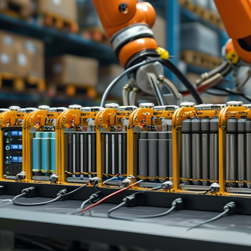
How to Choose the Right Robot Capacitor?
Robot Capacitor Requirements and Operating Conditions
A robot capacitor must match the drive circuit, motor load, and working environment. Start with the DC-link voltage, not the catalog label. Select a voltage rating above the highest measured bus voltage, including regenerative spikes. A narrow margin can cause early failure.
Ripple current is equally important. Fast acceleration creates sharp current pulses and extra heat inside the capacitor. Check the expected ripple current at the real switching frequency. Then compare it with the rated value at the robot’s actual temperature. Bigger is not always better.
Temperature matters greatly. A cabinet near a motor may exceed 50°C during long shifts. Use the capacitor’s lifetime data at that temperature, not only its room-temperature rating. High humidity, dust, vibration, and repeated power cycles also affect selection. Sealing and mechanical support deserve attention.
Watch the mounting position.
In practical testing, measure bus voltage, ripple current, case temperature, and vibration together. Software estimates can miss short regenerative events. I have seen designs pass bench tests but fail after months of continuous motion. The weak point was not capacitance. It was poor cooling and loose mechanical support.
Allow space for airflow and inspection. Confirm terminal torque and wiring length. Long connections can add inductance and create voltage overshoot. A controlled endurance test under maximum payload provides more reliable evidence than a single startup test. Some assumptions will be wrong. Review them after field data arrives.
Stored energy in a DC-link capacitor increases with capacitance and the square of bus voltage: E = ½CV². The values below show the approximate energy stored at a 600 V DC bus, which is useful when evaluating regenerative braking, peak power demand, and discharge safety.
How to Choose the Right Robot Capacitor?
Capacitance, voltage, and current ratings directly affect a robot’s motion stability. According to the International Federation of Robotics’ World Robotics 2024 report, 541,302 industrial robots were installed globally in 2023. More robots mean more compact drives, faster acceleration, and sharper electrical transients. Choose capacitance by measuring the drive’s peak load, braking energy, and allowable voltage ripple. A larger capacitor is not always safer. It can increase inrush current and extend discharge time.
Voltage selection needs practical margin. Keep the capacitor’s rated voltage above the highest measured DC-link voltage, including regeneration spikes. A 20% margin is a useful starting point, but real systems may require more. Temperature changes the result. Electrolytic capacitors often lose useful life quickly near their maximum temperature, so review the manufacturer’s lifetime curve and IEC 60384 requirements. I once underestimated heat near a motor brake resistor; the calculated capacitance looked correct, but the enclosure temperature was not.
Ripple current deserves equal attention. Check both RMS ripple current and high-frequency pulse current. Excess ripple creates internal heat, which accelerates aging. Measure the waveform with a properly rated probe during acceleration, stopping, and repeated direction changes. Do not rely only on nominal motor current. A capacitor can meet the voltage specification and still fail from ripple heating. The design may work. The margin may not.
| Capacitor Type | Typical Capacitance Range | Typical Voltage Range | Ripple Current Capability | ESR Characteristics | Recommended Robot Applications | Main Selection Considerations |
|---|---|---|---|---|---|---|
| Multilayer Ceramic Capacitor (MLCC) | Approximately 1 pF to 100 µF, depending on dielectric, case size, and rated voltage | Typically 6.3 V to 3,000 V | High-frequency ripple is generally handled well; allowable current depends on package size, temperature, and frequency | Very low ESR and ESL; suitable for high-frequency noise suppression | Motor-driver decoupling, sensor filtering, control boards, communication modules, and high-frequency switching circuits | Account for DC-bias capacitance loss, mechanical cracking risk, temperature characteristics, and acoustic noise |
| Aluminum Electrolytic Capacitor | Approximately 1 µF to 100,000 µF | Typically 6.3 V to 630 V | Moderate to high ripple-current ratings are available; heating must be checked carefully | Higher ESR than ceramic and film types; ESR increases as temperature decreases and with aging | DC-link energy buffering, power-supply smoothing, servo-drive bus filtering, and bulk storage | Check ripple current, expected lifetime, ambient temperature, mounting orientation, polarity, and maximum inrush current |
| Conductive Polymer Capacitor | Approximately 2.2 µF to 2,700 µF | Typically 2.5 V to 100 V | High ripple-current capability relative to size; verify the specified thermal limits | Low and stable ESR, providing effective transient response and output-voltage control | Compact DC-DC converters, embedded controllers, battery-powered robot electronics, and low-voltage motor-control rails | Confirm voltage derating, leakage current, temperature rating, reverse-voltage protection, and required capacitance at operating bias |
| Film Capacitor | Approximately 1 nF to 1,000 µF | Typically 50 V to 2,000 V or higher, depending on construction | Very good pulse and high-frequency ripple performance; current is limited by temperature rise and construction | Very low ESR and low dielectric loss; stable under repetitive pulses | Motor inverter snubbers, EMI filters, regenerative-braking circuits, resonant converters, and precision timing networks | Evaluate physical size, pulse voltage, dv/dt rating, self-healing behavior, temperature range, and mechanical vibration resistance |
| Electric Double-Layer Capacitor (Supercapacitor) | Approximately 0.1 F to several thousand farads per cell | Usually about 2.3 V to 3.0 V per cell; series balancing is required for higher system voltages | Very high short-duration current capability; continuous current depends on ESR and thermal limits | Low ESR for high-power bursts, but higher leakage current than conventional capacitors | Emergency actuator movement, peak-load support, energy recovery, power-fail ride-through, and robotic braking systems | Calculate usable energy using voltage limits, include cell balancing, control leakage, and provide overvoltage protection |
| Tantalum Capacitor | Approximately 0.1 µF to 2,200 µF | Typically 2.5 V to 125 V | Moderate ripple-current capability; high ripple and surge conditions require careful verification | Low to moderate ESR; polymer versions generally provide lower ESR than conventional versions | Space-constrained control electronics, stable low-voltage rails, and compact embedded modules | Use conservative voltage derating, limit surge current, observe polarity, and assess failure-mode requirements |
| Specification | How to Determine the Requirement | Practical Selection Guidance |
|---|---|---|
| Capacitance | Determine the required filtering, energy storage, load-transient response, and allowable voltage ripple. | For a capacitor supplying a transient load, estimate capacitance with C = I × Δt ÷ ΔV, then verify the result using the manufacturer’s bias, temperature, and frequency data. |
| Rated Voltage | Use the maximum continuous voltage, switching overshoot, regenerative voltage, and fault transients in the circuit. | Choose a voltage rating above the maximum measured operating voltage and apply additional derating for high temperature, frequent transients, and long service life. |
| Ripple Current | Calculate the RMS AC current through the capacitor over the complete switching and motion cycle. | Select a ripple-current rating at the actual operating frequency and temperature; excessive ripple causes internal heating and reduces lifetime. |
| ESR and ESL | Assess allowable voltage ripple, transient response, switching frequency, and pulse current. | Use low-ESR capacitors for fast current changes, but check stability and damping because an extremely low ESR can affect some regulator control loops. |
| Temperature and Lifetime | Estimate ambient temperature, enclosure temperature, self-heating, duty cycle, and required operating hours. | Use the capacitor’s lifetime model and keep the hotspot temperature within the specified limit; provide airflow or thermal paths where necessary. |
| Polarity and Safety | Identify whether the circuit can apply reverse voltage, abnormal charging, or high-energy discharge. | Use non-polar capacitors for bipolar signals; for polarized types, add reverse-voltage, overvoltage, inrush-current, and discharge protection. |
| Mechanical and Environmental Conditions | Consider vibration, shock, humidity, dust, connector movement, available PCB area, and mounting orientation. | Choose a suitable case size and mounting method, secure heavy components, and verify endurance under the robot’s actual motion profile. |
Selecting the right capacitor type starts with the robot’s electrical job, not its physical size. The International Federation of Robotics reported 541,302 industrial robots installed worldwide in 2023, with 4.28 million units operating globally. More robots mean more servo drives, regenerative braking events, and high-frequency switching demands. Each function stresses capacitors differently.
For a robot’s DC link, aluminum electrolytic capacitors provide high capacitance in a compact volume. They suit energy storage, but heat and ripple current can shorten their service life. Film capacitors usually handle higher ripple currents and rapid voltage changes, making them strong candidates for demanding drive circuits. They are larger and often cost more. Ceramic capacitors work well near processors and sensors because their low impedance suppresses high-frequency noise. However, their effective capacitance can fall sharply under DC bias. Small details matter.
IEC 61071 emphasizes electrical, thermal, and mechanical performance for power electronic capacitors. In practice, engineers should check voltage margin, ripple current, ambient temperature, vibration, and expected switching frequency. A 20–30% voltage margin is a useful starting point, not a universal rule. For electrolytic parts, measure the hottest internal location, not just room temperature. The choice can still be imperfect. A smaller capacitor may save space but increase thermal stress. A larger one may improve reliability but disturb balance and mounting. My checklist would also include regenerative energy measurements, because calculated peaks often miss real motion profiles.
Choosing a robot capacitor starts with the electrical duty cycle, not the component’s label. Measure bus voltage, ripple current, switching frequency, and enclosure temperature during real motion. A capacitor that fits the circuit board may fail inside a warm cabinet.
Size includes capacitance, ripple rating, terminal spacing, and vibration resistance. Select voltage with practical headroom; repeated surges can damage dielectric layers. IEC 60384 series standards define capacitor qualification and testing requirements. For insulation, IEC 60664-1 helps determine clearance and creepage distances. These standards do not replace application testing, which is where many designs become less certain.
Temperature strongly affects lifetime. A common engineering estimate says life may double for every 10°C reduction, but this rule is not universal. Check the manufacturer’s life model and test conditions. The IEC 60068-2 environmental testing series covers temperature cycling and vibration methods relevant to mobile equipment. Also compare ripple current at the actual frequency. Heat generated by ESR is often underestimated.
Tips: Log temperature near the capacitor during peak acceleration. Use a capacitor rated above the measured ripple current. Review vent direction and pressure relief. For safety, follow IEC 60204-1 for machine electrical equipment and add discharge protection where stored energy remains hazardous. I would not trust a catalog lifetime alone. Real robots stop, start, reverse, and vibrate unpredictably. That detail matters.
A suitable robot capacitor must match capacitance, voltage rating, ripple current, and temperature range. Check the robot’s service manual and measure the existing part before ordering. Never select a capacitor by size alone. A larger value may affect charging current, braking response, or controller protection. Confirm polarity on polarized capacitors. Mark the positive and negative wires before removal. Small labels prevent expensive mistakes.
Switch off the robot and isolate every power source. Allow the DC bus to discharge according to the equipment procedure. Verify zero voltage with a properly rated meter. Do not trust indicator lights. They can remain dark while dangerous energy is present. Wear suitable eye protection and use insulated tools. Inspect the terminals for heat marks, loose crimps, or swollen insulation. These details often reveal a deeper fault.
Install the capacitor firmly, without bending its terminals. Keep cables short and separate from sharp edges. Check torque against the maintenance specification. Then test capacitance and equivalent series resistance with a suitable meter. Compare the readings with the manufacturer’s tolerance. Reconnect power through the approved precharge circuit. Watch the startup current, DC-bus voltage, and unusual sounds. A thermal camera can reveal one hot terminal after several motion cycles. Repeat the test under real robot movement, not only at idle. I still recheck polarity twice. It takes seconds. A useful improvement is recording voltage, temperature, and test conditions. Without those notes, later troubleshooting becomes guesswork.
Hein Minnie
Cell nr: +27 (0) 82 564 6501
Email: sale@thecirclemachine.com
Hein Minnie Jnr
Cell nr: +27 (0) 84 284 7234
Email: sale@thecirclemachine.com
Address:
10 Apsey Street,
Heidelberg,
Gauteng,
1441
Bendet Engineering Services (PTY) LTD was established in 1987. Our team of engineers and draughtsman are ready to deliver a complete turnkey solution, from the design phase to commissioning. A dedicated team that consists of electrical, mechanical and industrial engineers, we are able to offer a comprehensive service to our clients.