








Choosing among the 10 Best Substation Transformers for Global Buyers requires more than comparing price tags and nameplate ratings. These assets connect generation, transmission, and distribution networks, often operating continuously in demanding environments. A suitable transformer must match voltage levels, load profiles, cooling methods, installation space, and local climate conditions. Small details matter.
This introduction frames a practical review of Substation Transformers from an engineering and procurement perspective. It considers core construction, insulation systems, efficiency, noise control, monitoring technology, fire safety, and expected service life. It also examines factory testing, certification, warranty terms, spare-parts support, and the manufacturer’s ability to provide commissioning assistance. Buyers should request verified test reports, clear technical drawings, and realistic delivery schedules before approving a purchase.
The strongest product is not automatically the largest or most expensive model. A compact transformer may suit an urban substation, while a sealed outdoor unit may better withstand dust, humidity, and temperature swings. Oil-immersed designs can offer proven performance, but maintenance planning remains essential. Dry-type options may simplify indoor installation, although their cost and thermal limits require careful review. Not every brochure tells the full story.
The following overview compares ten widely considered options using practical selection criteria, manufacturer credibility, operational resilience, and long-term ownership value. It avoids unsupported rankings where regional data is limited. Buyers should still confirm grid codes, environmental requirements, and independent test results with qualified engineers. Real projects vary. That is where careful judgment matters.
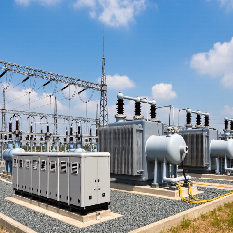
A substation transformer is a static electrical device that transfers energy between circuits through electromagnetic induction. It raises voltage for efficient transmission and lowers it for safer distribution. Frequency remains unchanged. The voltage ratio follows the turns ratio between the high-voltage and low-voltage windings.
Its operating principle is practical, not mysterious. Alternating current creates a changing magnetic flux inside the core. That flux induces voltage in the secondary winding. Core losses occur continuously, while copper losses increase with load current. Heat matters. Oil or other approved insulating fluids remove heat and strengthen electrical insulation. Radiators, fans, and temperature monitors support stable operation. On-load tap changers adjust voltage during demand changes, but poor maintenance can accelerate contact wear.
The IEA Electricity 2024 report projects global electricity demand growth of about 3.3% annually through 2026. This pressure makes dependable substation capacity increasingly important. Buyers should compare rated power, voltage class, impedance, cooling method, insulation level, sound limits, and short-circuit withstand capability. IEC 60076 provides the main testing and performance framework for power transformers. CIGRE technical guidance also highlights condition monitoring, dissolved-gas analysis, and moisture control as valuable reliability tools. Field experience shows that nameplate capacity alone is not enough. Ambient temperature, harmonics, emergency loading, and grid fault levels can change the real duty. A rushed specification may look efficient on paper. It may not survive the actual network.
The chart presents ten representative preferred power ratings used for substation transformers, expressed in megavolt-amperes (MVA). These ratings are selected from standardized rating series referenced by IEC 60076-1. Actual transformer selection depends on system voltage, load demand, short-circuit conditions, cooling method, redundancy requirements, and future expansion plans.
10 Best Substation Transformers for Global Buyers
Transformer Types and Selection Criteria for International Substation Projects
Selecting the right substation transformer starts with the project’s voltage, load profile, and grid conditions. Oil-immersed transformers suit large outdoor substations and high-capacity transmission duties. Dry-type transformers can reduce fire risks in buildings, tunnels, and compact urban facilities. Autotransformers may improve efficiency where voltage ratios remain relatively close. Three-winding designs support multiple voltage levels and auxiliary loads.
International buyers should examine rated power, insulation level, short-circuit strength, cooling method, noise limits, and installation altitude. Seismic requirements also matter in vulnerable regions. Confirm compliance with applicable IEC or regional standards before comparing quotations. Ask for verified routine and type-test records. Review temperature-rise data, loss calculations, protection interfaces, and spare-parts availability. A low purchase price can hide higher lifetime costs. That mistake is common.
Tips: Build a clear technical schedule before requesting offers. Include ambient temperature, humidity, altitude, transportation limits, tap-changer needs, and expected future loading. Check whether the transformer can pass through local roads, bridges, and substation gates. Request drawings early. Small dimensions can create large site problems. Consider factory inspection and independent testing for critical projects. Keep communication precise, because translation gaps may affect cooling, bushing, or protection requirements. No selection checklist is perfect; real operating data should challenge the original assumptions.
| No. | Transformer Type | Best-Fit Application | Typical Power Rating | Typical Voltage Range | Cooling and Insulation | Regulation / Configuration | Main Advantages | Key Selection Checks for International Projects |
|---|---|---|---|---|---|---|---|---|
| 1 | Two-Winding Oil-Immersed Power Transformer | Transmission and distribution substations requiring a reliable step-up or step-down connection. | 10–1,000 MVA | Typically 6.6–550 kV; higher voltage classes are available for specialized grids. | Mineral oil or ester liquid; ONAN, ONAF, OFAF or ODAF cooling, depending on rating. | Fixed ratio or on-load tap changer (OLTC), commonly on the high-voltage winding. | Broadest application range, mature technology, high efficiency and strong overload capability. | System short-circuit level, impedance, vector group, insulation coordination, cooling duty, transport limits and local grid code. |
| 2 | Three-Winding Power Transformer | Substations connecting transmission, sub-transmission and auxiliary or industrial voltage levels. | 20–500 MVA total rating, subject to winding-loading combinations. | Common combinations include 220/110/10 kV and 132/33/11 kV. | Oil-immersed construction with ONAN/ONAF or forced-oil cooling. | Separate HV, LV and tertiary windings; OLTC may be installed on the regulating winding. | Reduces the need for multiple transformers and can provide a dedicated tertiary winding for reactive compensation or station service. | Winding loading combinations, tertiary fault duty, zero-sequence impedance, phase displacement, circulating-current risk and protection scheme. |
| 3 | Autotransformer | Interconnecting two transmission voltages with a relatively small voltage ratio, such as 400/220 kV or 220/132 kV. | 100–1,000 MVA | Usually 110–550 kV on the high-voltage side. | Oil-immersed; ONAN, ONAF, OFAF or ODAF cooling. | Commonly equipped with an OLTC; electrically common HV and LV windings. | Lower material usage, smaller footprint, lower losses and higher efficiency than an equivalent two-winding transformer for suitable ratios. | Absence of galvanic isolation, common-winding fault current, neutral insulation, transfer voltage and system grounding requirements. |
| 4 | Phase-Shifting Transformer | Controlling active-power flow between parallel corridors, preventing loop flows and improving transmission utilization. | 100–1,200 MVA | Typically 110–550 kV, depending on the transmission network. | Oil-immersed with forced cooling for high-load operation. | Mechanically or electrically controlled phase-angle regulation, often combined with voltage regulation. | Improves controllability, relieves congestion and helps manage cross-border or parallel-path power flows. | Phase-angle range, through-current rating, fault forces, tap-changer duty, control-system interoperability and dynamic network studies. |
| 5 | On-Load Tap-Changing Transformer | Distribution and transmission substations where voltage must be regulated while energized and loaded. | 10–500 MVA | Commonly 33–400 kV on the high-voltage side, with the tap range often around ±10% to ±15%. | Oil-immersed main tank; separate or in-tank tap changer compartment depending on design. | Automatic voltage regulation without supply interruption; typical tap steps are approximately 1.0%–1.5%. | Maintains bus voltage under changing load and renewable-generation conditions. | Tap range, switching endurance, transient recovery voltage, regulator compatibility, bypass arrangements, maintenance access and control voltage. |
| 6 | Cast-Resin Dry-Type Transformer | Indoor substations, commercial buildings, hospitals, tunnels, offshore facilities and locations with strict fire or spill-control requirements. | 100 kVA–40 MVA | Typically up to 36 kV for medium-voltage distribution applications. | Cast-resin solid insulation; AN or AF air cooling. | Usually off-circuit taps; optional voltage adjustment arrangements are available for selected designs. | No liquid leakage, low fire risk, simplified indoor installation and reduced civil-engineering requirements. | Ambient temperature, altitude, enclosure IP rating, acoustic limits, partial-discharge level, ventilation, fire classification and overload profile. |
| 7 | Mobile Substation Transformer | Emergency replacement, temporary grid reinforcement, disaster recovery, planned maintenance and remote projects. | 5–200 MVA | Commonly 33–230 kV, with the final range determined by the transportable design. | Compact oil-immersed construction; cooling and accessories optimized for rapid deployment. | Fixed taps or OLTC; designed for connection to temporary switchgear and protection systems. | Fast deployment, operational flexibility and reduced outage duration. | Road and rail axle limits, dimensions, lifting points, transport permits, rapid commissioning, connector compatibility, grounding and environmental conditions. |
| 8 | Grounding / Earthing Transformer | Creating a neutral point on an ungrounded or delta-connected network and limiting earth-fault current. | Typically 100 kVA–30 MVA; short-time ratings are often specified for 10 seconds. | Commonly 6.6–33 kV, with higher-voltage designs available for specific networks. | Oil-immersed or dry-type; cooling selected for continuous and short-time duty. | Zigzag or interconnected-star winding, often combined with a neutral grounding resistor or reactor. | Provides a controlled earth-fault path and improves protection sensitivity and system stability. | Zero-sequence impedance, neutral current and duration, resistor coordination, transient overvoltage, insulation level and protection settings. |
| 9 | Converter Transformer | HVDC converter stations, large variable-speed drives, electrolysis plants and high-power rectifier systems. | 100–1,000 MVA per transformer unit, depending on converter topology. | AC system voltages commonly range from 110–500 kV; valve-side voltage depends on the converter design. | Special oil-paper insulation with forced cooling and enhanced thermal monitoring. | Single-phase or three-phase units; phase-shifted secondary windings may be used for multipulse arrangements. | Designed for harmonic currents, DC-related stresses and demanding cyclic load conditions. | Harmonic spectrum, DC bias, leakage reactance, insulation stress, acoustic noise, cooling redundancy, valve-side bushings and converter control requirements. |
| 10 | Traction Substation Transformer | Railway traction substations supplying AC or DC railway electrification systems. | 5–100 MVA per unit, depending on railway voltage and traffic demand. | Primary side commonly 66–220 kV; secondary systems may include 25 kV, 2×25 kV or other railway-specific voltages. | Oil-immersed or dry-type; cooling selected for frequent load changes and high short-time demand. | Single-phase, three-phase, Scott-connected or other specialized configurations; OLTC may be required. | Handles rapid load variation, regenerative braking effects and railway-specific power-quality requirements. | Load-cycle profile, negative-sequence current, harmonics, unbalance, short-circuit duty, railway earthing, insulation coordination and electromagnetic compatibility. |
Engineering note: The ratings and voltage ranges shown are typical market application ranges rather than universal limits. Final selection should be verified against the project network study, applicable grid code, climate and altitude data, transport constraints, environmental requirements, and relevant standards such as IEC 60076 or IEEE C57 series.
Global buyers can compare ten practical substation transformer options. Oil-immersed power transformers suit high-voltage networks and outdoor installations. Dry-type transformers reduce fire concerns inside buildings and urban substations. Cast-resin units resist moisture and need limited routine maintenance. Three-winding transformers support several voltage levels from one enclosure. Autotransformers offer efficient voltage conversion where electrical isolation is unnecessary.
Fit varies. A traction transformer serves railway networks with frequent load changes. Mobile transformers provide temporary capacity after failures, construction, or planned outages. Phase-shifting transformers help control power flow between interconnected transmission corridors. Shunt reactors manage excessive line voltage during light-load conditions. Amorphous-core transformers can reduce no-load losses in suitable applications.
Record system voltage, short-circuit level, ambient temperature, altitude, load profile, and available space. Check impedance, cooling stages, tap-changer range, noise limits, and bushing clearances. Factory routine tests should support traceability, while independent inspections can strengthen purchasing confidence. Ask for temperature-rise results, partial-discharge data, oil quality records, and transport dimensions.
Installation experience shows that accessories often decide availability. A blocked radiator, undersized cable box, or poorly protected control cabinet can delay energization.
Standards matter, but local grid rules may add stricter requirements. Not every site agrees. A technically strong choice can still fail commercially when spare parts, service skills, or delivery routes are limited.
I would also review lifecycle losses, emergency loading, cybersecurity for digital controls, and end-of-life handling. The perfect transformer rarely exists; the most defensible option matches verified risk, budget, and operating reality.
Selecting the 10 best substation transformers requires more than comparing nameplate capacity. Global buyers should examine efficiency, thermal stability, safety design, and documented compliance. A transformer may perform well at sea level but struggle at high altitude or in extreme heat. Check load losses, no-load losses, impedance, cooling capacity, and short-circuit strength. Field engineers should also review temperature-rise records, vibration levels, and factory acceptance data.
Safety details deserve close attention. Look for pressure-relief devices, fire-resistant materials, oil containment, clearances, and reliable monitoring systems. Dry-type units can suit indoor sites, while oil-immersed units may offer stronger high-voltage performance. Local grid codes, IEC or IEEE requirements, environmental rules, and utility specifications must match the purchase contract. Certificates alone are not enough. Test scopes, calibration records, and traceable serial documentation matter.
Efficiency affects operating costs for decades. Compare lifecycle losses, not only the initial price. A small saving at purchase can become an expensive burden under continuous loading. Ask for guaranteed loss values and realistic temperature data. I have seen spreadsheets hide poor ventilation assumptions. That deserves scrutiny. Buyers should inspect maintenance access, spare-part support, noise data, and installation procedures. No comparison is perfect; site conditions often change the final ranking.
10 Best Substation Transformers for Global Buyers?
Purchasing, Installation, Maintenance, and Lifecycle Cost Considerations
Choosing among the ten best substation transformers requires more than comparing purchase prices. Start with the network profile: voltage ratio, load curve, fault level, ambient temperature, altitude, and expected expansion. A 33/11 kV transformer may suit one utility, while another needs different impedance and cooling capacity. Request verified test reports, efficiency data, warranty terms, spare-part availability, and compliance with applicable electrical standards. Delivery distance matters too. A cheaper unit can become expensive after customs, transport, insurance, and site delays.
Installation quality strongly affects service life. Confirm foundation dimensions, cable clearances, earthing, lifting points, and fire-protection arrangements before delivery. Keep the transformer dry during storage. Check oil level, bushings, tap-changer operation, protection relays, and insulation resistance before energizing. An experienced commissioning engineer should record baseline readings, not just sign a checklist. Small oversights become loud problems.
Maintenance planning should include thermal scans, oil sampling, leak inspections, bushing checks, and relay testing at defined intervals. Online monitoring may justify its cost on critical substations, but not every site needs the same sensors. Calculate lifecycle cost using losses, maintenance labor, outage risk, oil treatment, spare components, and eventual disposal. I have seen buyers underestimate downtime while overpaying for unused features. No spreadsheet predicts every failure. Leave room for engineering judgment, local skills, and uncomfortable questions.
Hein Minnie
Cell nr: +27 (0) 82 564 6501
Email: sale@thecirclemachine.com
Hein Minnie Jnr
Cell nr: +27 (0) 84 284 7234
Email: sale@thecirclemachine.com
Address:
10 Apsey Street,
Heidelberg,
Gauteng,
1441
Bendet Engineering Services (PTY) LTD was established in 1987. Our team of engineers and draughtsman are ready to deliver a complete turnkey solution, from the design phase to commissioning. A dedicated team that consists of electrical, mechanical and industrial engineers, we are able to offer a comprehensive service to our clients.